
mRCH Monitor — 120V
What you are installing
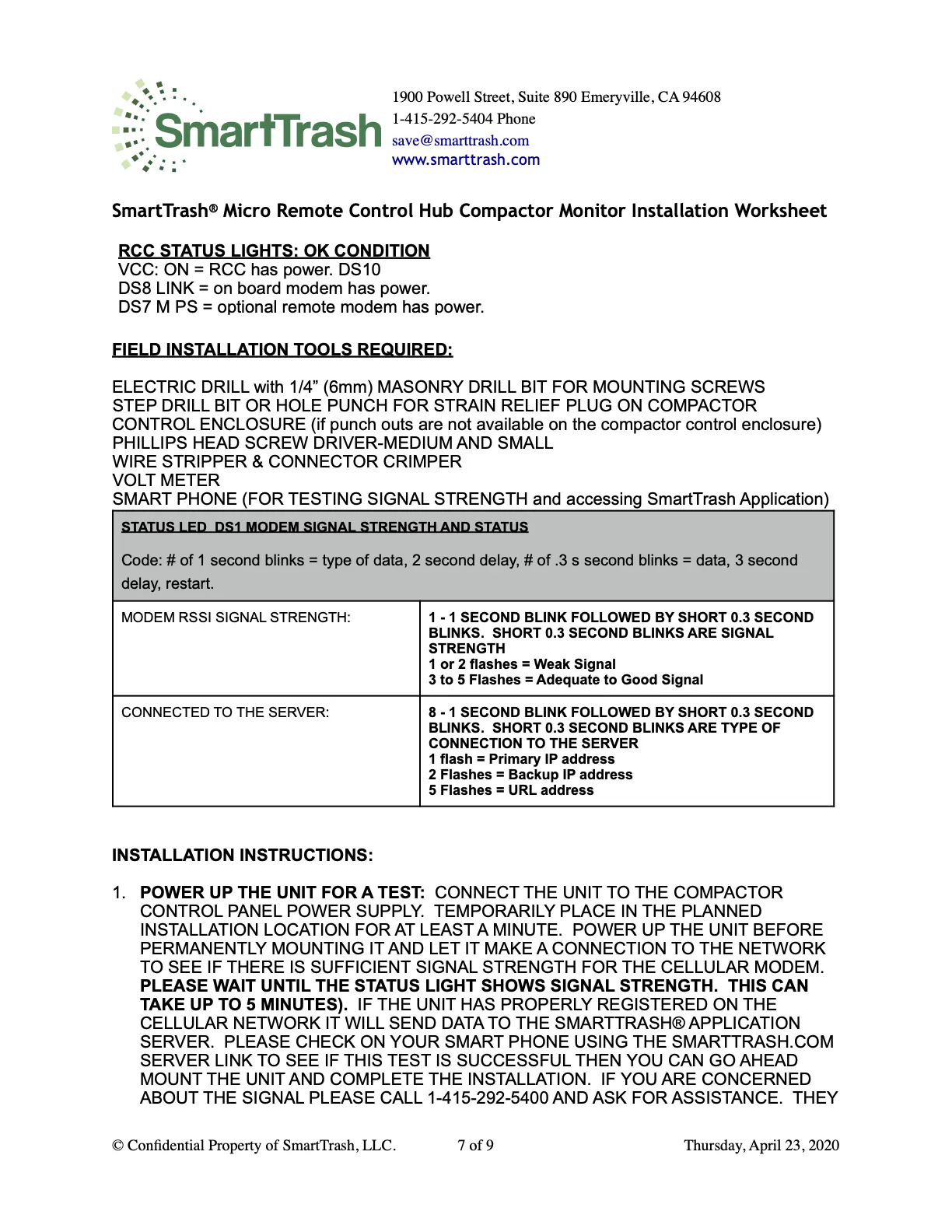
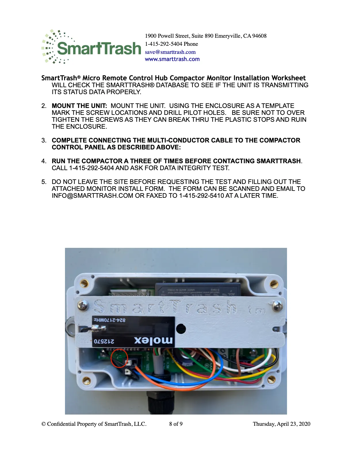
SmartTrash® is a UL/CE approved watertight enclosure with a power supply (115V 60Hz to 230V), a proprietary Micro RCH circuit board, and an onboard wireless LTE modem.
A UL/CE approved 22AWG 300VAC multi-conductor UV/oil/flame-resistant cable connects the Micro RCH board to the compactor control panel.
AC control panel wiring
The unit uses the same AC Neutral reference for all inputs. If that is not true for this panel, contact SmartTrash before wiring.
Standard 120V monitors cannot be used with 24V compactors — use the 24V SmartTrash Monitor instead.
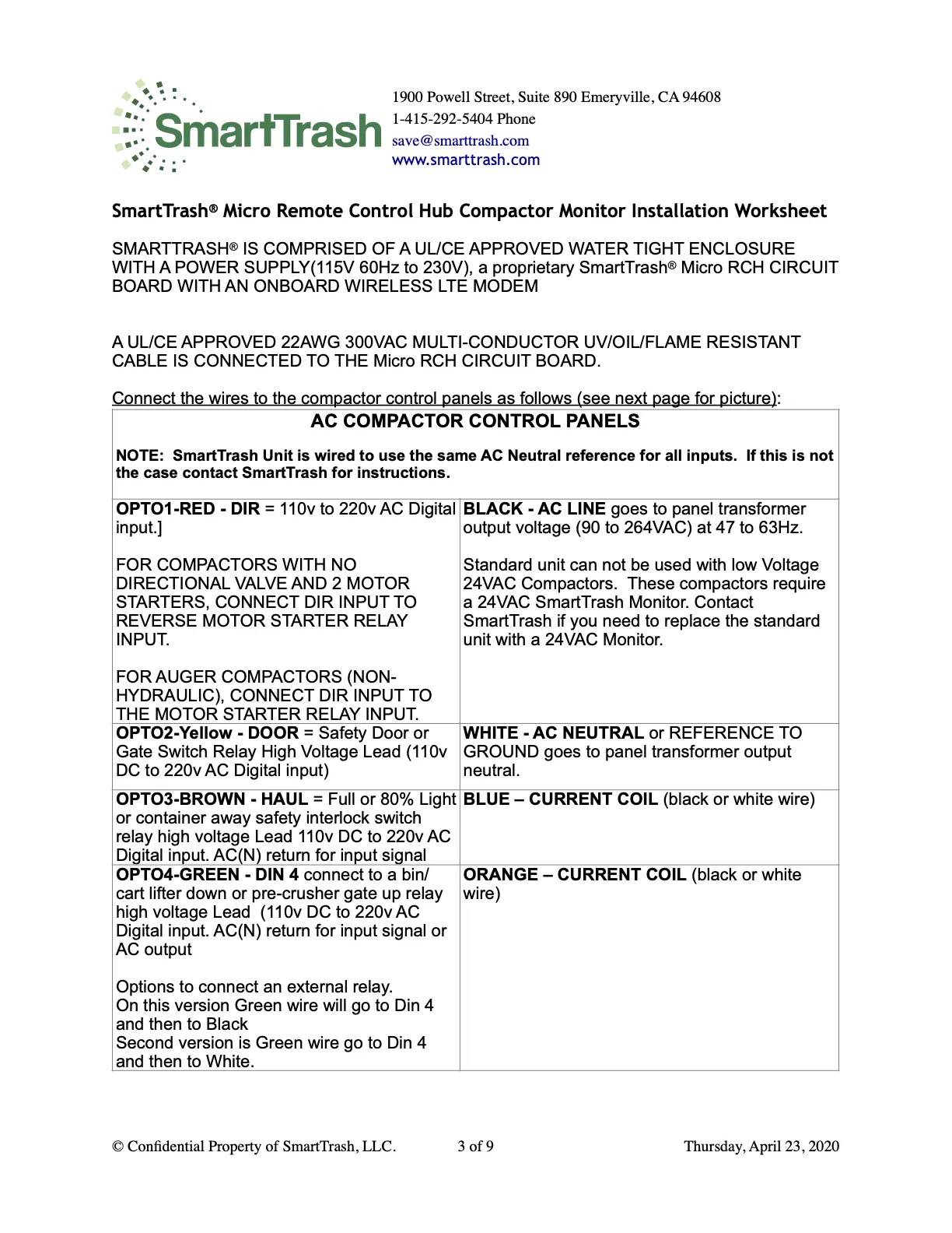
- OPTO1 — RED (DIR): 110–220V AC digital input. No directional valve with 2 motor starters → connect DIR to the reverse motor starter relay input. Auger (non-hydraulic) → connect DIR to the motor starter relay input.
- BLACK (AC LINE): panel transformer output (90–264VAC, 47–63Hz).
- OPTO2 — YELLOW (DOOR): safety door or gate switch relay high-voltage lead (110V DC–220V AC).
- WHITE (AC NEUTRAL): panel transformer output neutral / reference to ground.
- OPTO3 — BROWN (HAUL): full / 80% light or container-away interlock (110V DC–220V AC).
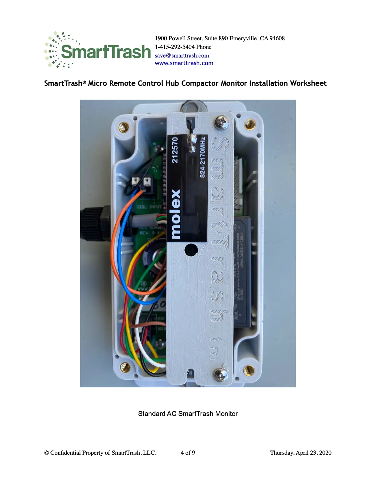
- BLUE / ORANGE: current coil leads (black or white wire on the sensor).
- OPTO4 — GREEN (DIN 4): bin/cart lifter down or pre-crusher gate relay (110V DC–220V AC). Green may land on Din 4 then Black, or Din 4 then White, depending on relay option.
Parts & enclosure
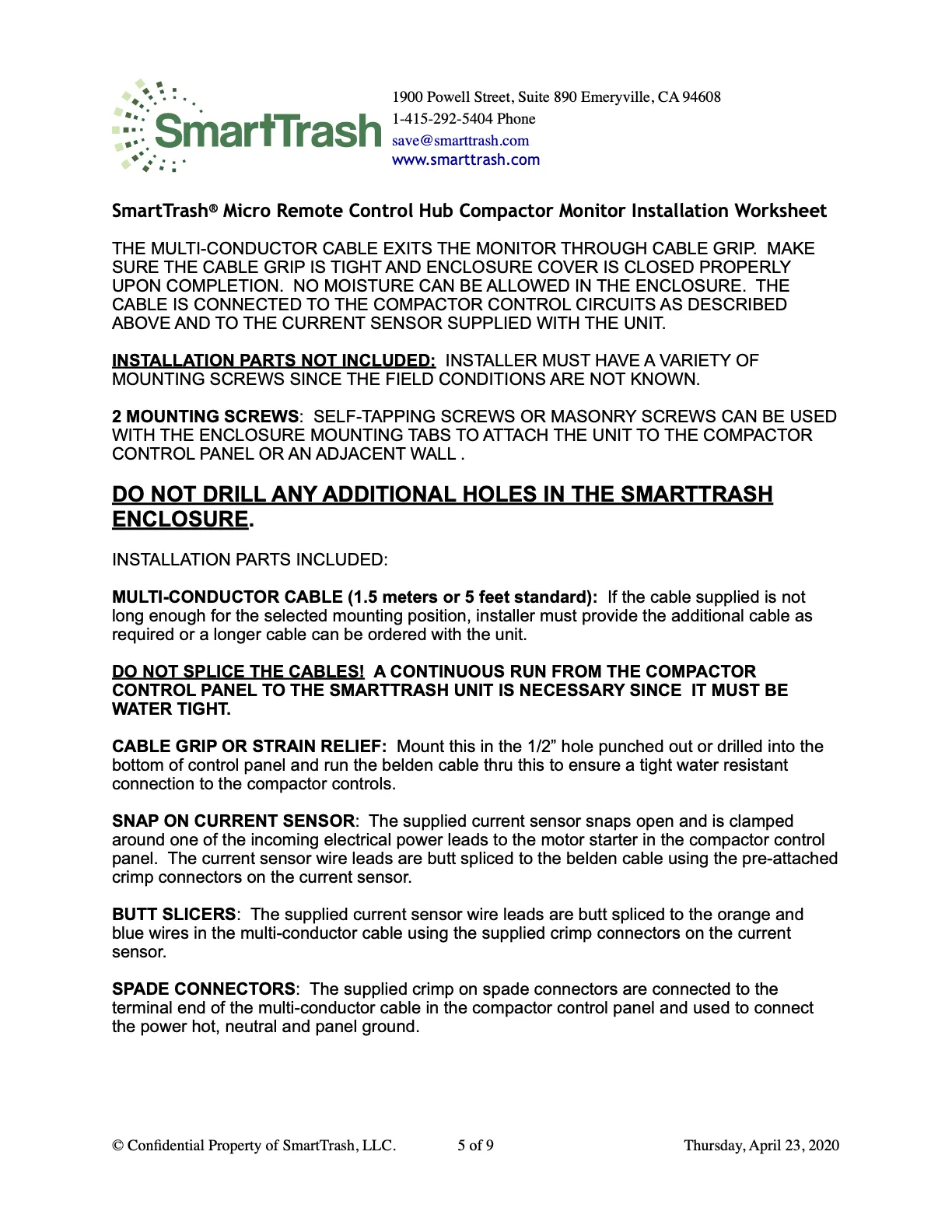
The multi-conductor cable exits through the cable grip. Keep the grip tight and the enclosure cover closed — no moisture inside the enclosure.
Do not drill additional holes in the SmartTrash enclosure. Do not splice cables; use a continuous watertight run.
- Not included: mounting screws (self-tapping or masonry as needed).
- Included: multi-conductor cable (~5 ft / 1.5 m standard), cable grip / strain relief for a ½″ hole, snap-on current sensor, butt splices, spade connectors.
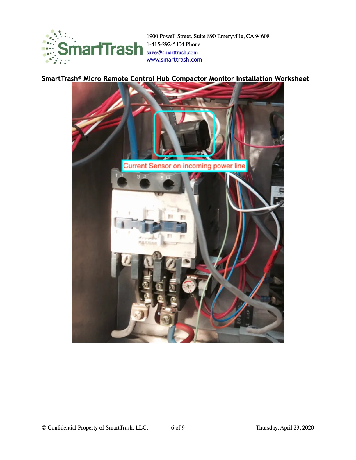
- Current sensor: clamp around one incoming power lead to the motor starter; butt-splice sensor leads to the orange and blue cable wires.
Installation steps
- Tools: electric drill with ¼″ masonry bit, step drill or hole punch for strain relief, Phillips screwdrivers, wire stripper & crimper, volt meter, smartphone.
- 1. Power-up test: connect to panel power, place temporarily at the planned location, wait up to 5 minutes for signal strength, confirm the unit appears in the SmartTrash application before permanent mount. Weak signal? Call 1-415-292-5404.
- 2. Mount the unit using the enclosure as a template. Do not overtighten screws.
- 3. Finish multi-conductor connections as described above.
- 4. Run the compactor three times, then call 1-415-292-5404 for a data integrity test.
- 5. Do not leave until you request the test and submit the install worksheet below.
Troubleshooting
- No DIR input: check continuity; watch voltage from start through ram reverse — there should be a change on retract.
- No E_RUN_DATA: current sensor voltage at the monitor should be 1–7V. Over 7V → notify SmartTrash to adjust sensitivity.
Installation worksheet
Do not leave the site until you request a data integrity test (1-415-292-5404) and submit this form.